
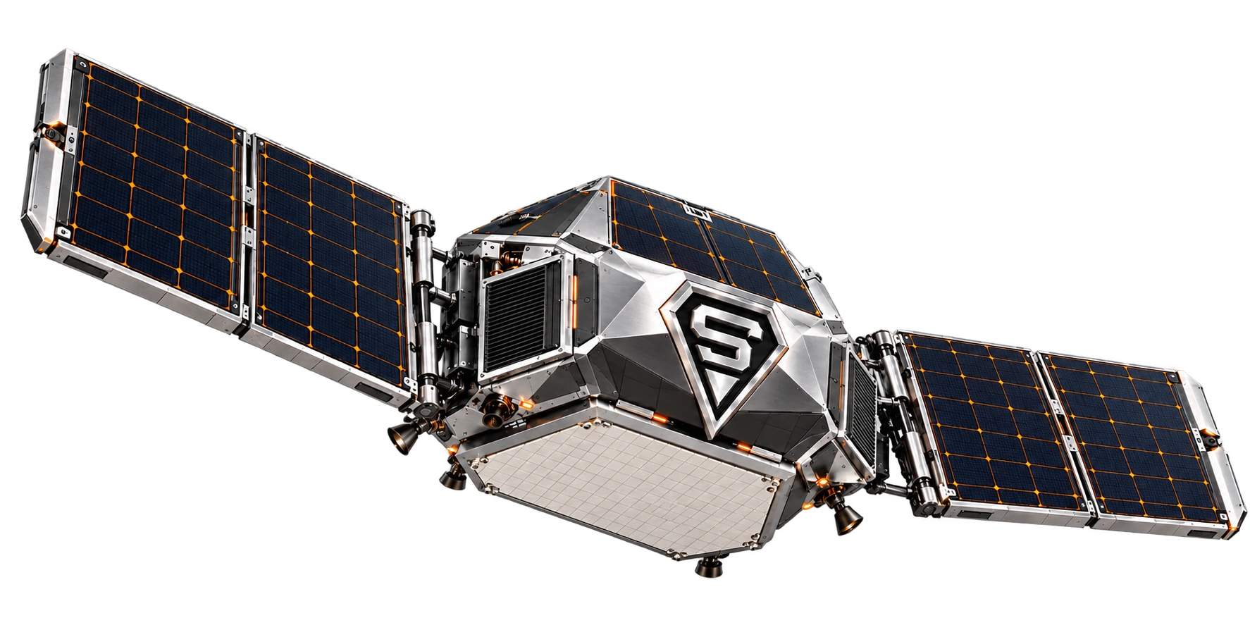
Spacecraft
S-Series studies explore larger and compact photovoltaic platforms with mission-selected payload interfaces.

SOFOS ORBIT™ / A DIVISION OF SOFOS INDUSTRIES
Satellite communications.
Spacecraft concepts.
© 2026 SOFOS INDUSTRIES. All Rights Reserved. S-Series designs and the SI diamond logo are trademarks owned by SOFOS INDUSTRIES.
01 / SOFOS ORBIT / S-SERIES
SOFOS Orbit brings communications equipment and the separately defined S-Series spacecraft concept programme into one space-focused division. The communications products connect ground sites, stationary vehicle deployments and separately qualified airborne payloads.
S-Series studies explore larger and compact photovoltaic platforms with mission-selected payload interfaces.
Ground interfaces, gateways and EBF communications sit within a mission-defined communications architecture.
Shared mission context and evidence support coordination across platforms, within each platform’s own authority and operating limits.
02 / COMMUNICATIONS / PRODUCT PROGRAMME
Six defined communications products support terminal connectivity, local control and mission integration. A network service, installation and maintenance entitlement remain separate from the equipment itself.
SELECT A PRODUCT TO EXPLORE ITS ROLE ↓
COM-VSAT01 / 01 OF 06
A mechanically steered VSAT terminal for the selected communications service. Local antenna control supports pointing.
Local control stays local.The antenna controller retains pointing, calibration and RF protection. QIOS provides authorised objectives through the communications gateway.
Interfaces match the mission.Frequency band, polarisation, steering sector, measured gain, link budget, beams, latency, power and temperature belong to the selected RF profile.
03 / S-SERIES / CONCEPT EXPLORER
The separately defined orbital spacecraft programme retains these two S-Series concept studies. They are distinct from the communications equipment above; payload, orbit and service characteristics follow their own programme definition.
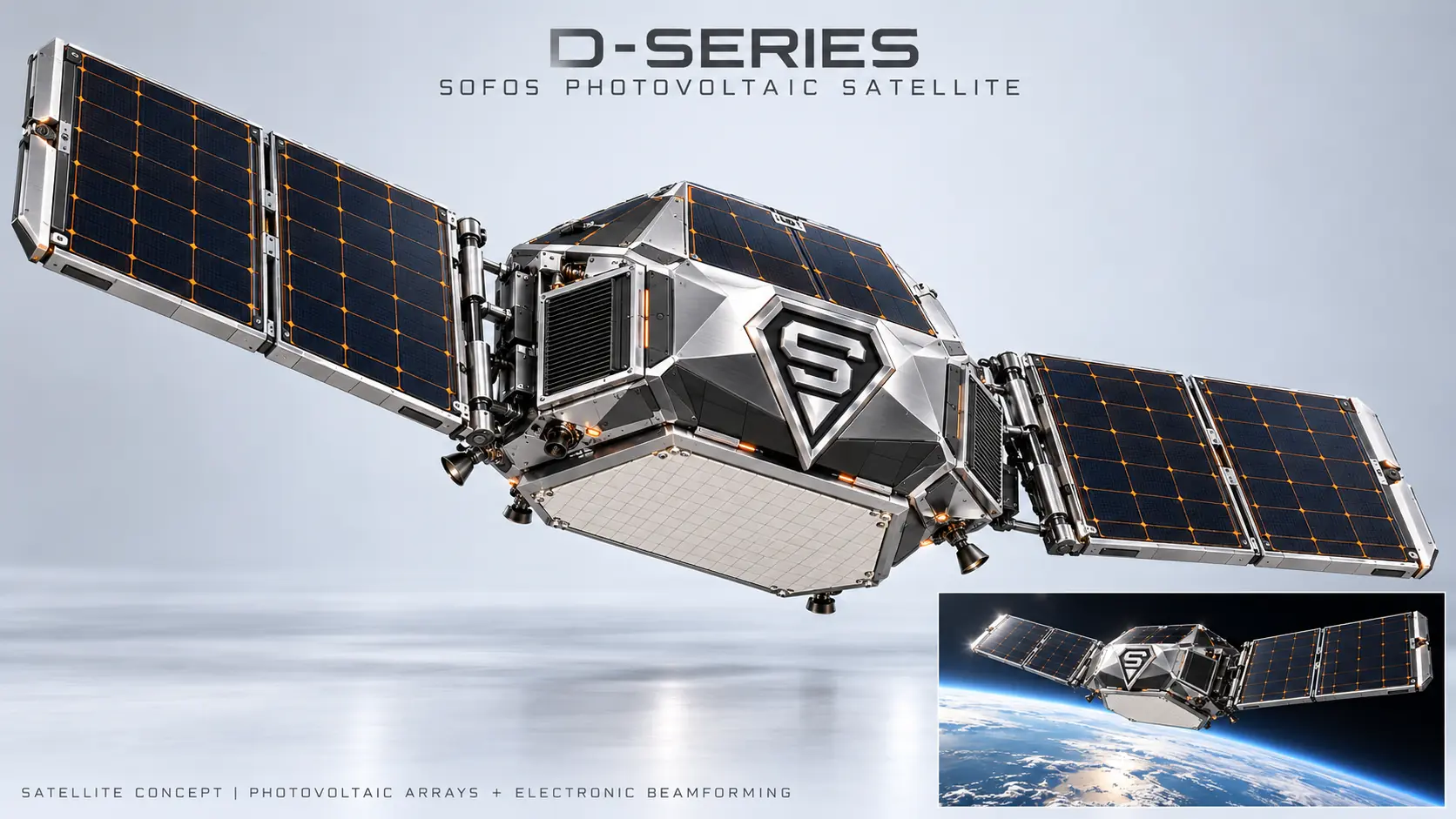
A larger photovoltaic platform study with deployed solar arrays and mission-selected communications payload interfaces.
SOFOS ORBITER 1 / SO1
A shoebox-form spacecraft concept. Photovoltaic arrays pack around the compact body, then open to an expansive mission configuration.
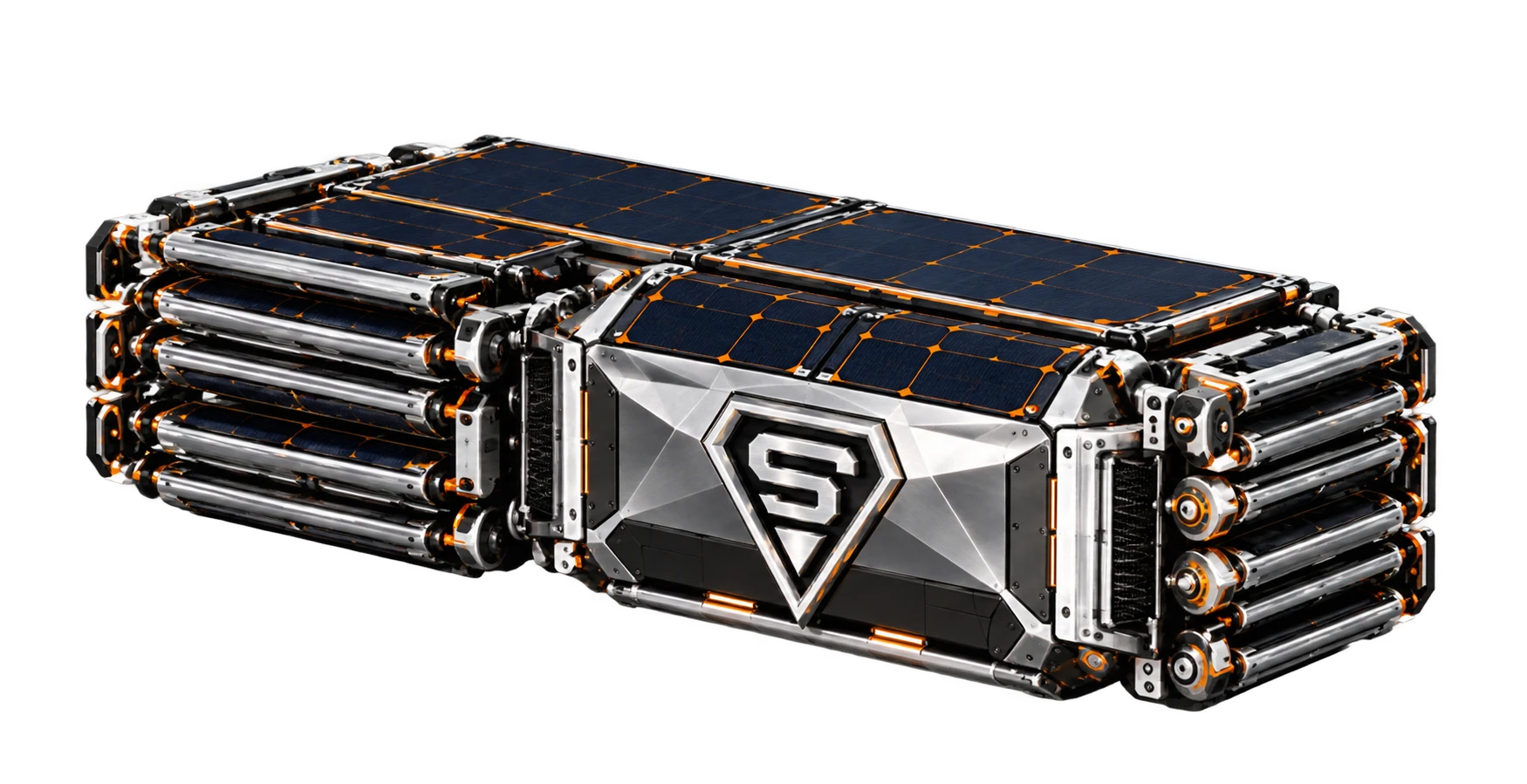
CONCEPT VISUALISATION · MOTION IS ILLUSTRATIVE; HINGES, PACKAGING AND DEPLOYMENT SEQUENCE REMAIN UNDER DEVELOPMENT. SHOEBOX-FORM DESCRIBES THE CONCEPT, NOT RELEASED DIMENSIONS.
© 2026 SOFOS INDUSTRIES. All Rights Reserved. All S-Series designs and the SI diamond logo are trademarks owned by SOFOS INDUSTRIES.
Breadcrumbs behind us. Better decisions ahead. / Panel 07 ↗04 / GROUND TO SPACE / AN ARCHITECTURE VIEW
Explore the parts of a mission-defined communications chain. This illustrates the architecture, rather than a live constellation or operational link.
SELECT A PART OF THE CONNECTION
A field platform connects to mission-selected communications services, supporting coordination between the field and the wider operation.
CONNECTED ACROSS PLATFORMS
Space, air and ground platforms can contribute to a shared mission. Each brings its own capabilities, operating limits and local control. Communications supports coordination across those domains.
05 / ELECTRONIC BEAMFORMING / CONTROLLER ARCHITECTURE
The controller programme combines timing, control interfaces, calibration storage, thermal telemetry and firmware with selected beamformer components.
EXPLORE ELECTRONIC STEERING
Move the control to explore the idea of steering a communications beam electronically. This graphic represents direction only.
CONCEPT DIAGRAM · NO MEASURED RF PATTERN OR STEERING LIMITS
Mission requirements and compatible equipment interfaces.
Timing, calibration, phase and amplitude control, with local RF protection.
Selected RF components and a matched antenna implementation.
The initial route uses commercially available RF devices and a compatible array. Custom RF silicon and array manufacture are separate development stages.
06 / DEPLOYMENT / POWER / SERVICE
Ground sites, stationary vehicles and airborne payloads have different integration requirements. Select the terminal, gateway, mounting, power profile and service entitlement for the actual deployment.
01 / DEPLOYMENT CONTEXT
Site and stationary vehicle deployments use their own mounting, power, cable and communications profiles. Available link capacity and network rights govern service.
The equipment and service profile follow the actual installation.
Discuss a ground deployment ↗PLANNED INDUSTRIALISATION
Gateway and controller assembly, authenticated firmware provisioning and calibrated RF testing form the communications electronics workstream. Serial records, manuals and service support follow the released configuration.
07 / BREADCRUMBS / MISSION CONTINUITY
As the mission moves forward, digital breadcrumbs preserve the experience of the journey. That accumulated understanding informs the next decision and strengthens the way ahead.
01 / 04
The mission begins. Each moment becomes part of its unfolding experience.
PROGRAMME CONCEPT · DESCRIBES THE INTENDED ROLE OF MISSION MEMORY; NOT A GUARANTEE OF SAFE OPERATION.
08 / PROJECT & PARTNER ENQUIRIES
Define what the operation needs. Prepare a short project brief to share with your SOFOS contact.